Cloud-electronics CX163 User Manual Page 8
- Page / 21
- Table of contents
- TROUBLESHOOTING
- BOOKMARKS
- Installation & Setup 1
- CLOUD ELECTRONICS LIMITED 3
- Table of Contents 5
- Table of Contents (continued) 6
- 1 Safety Notes 7
- 2 General Description 7
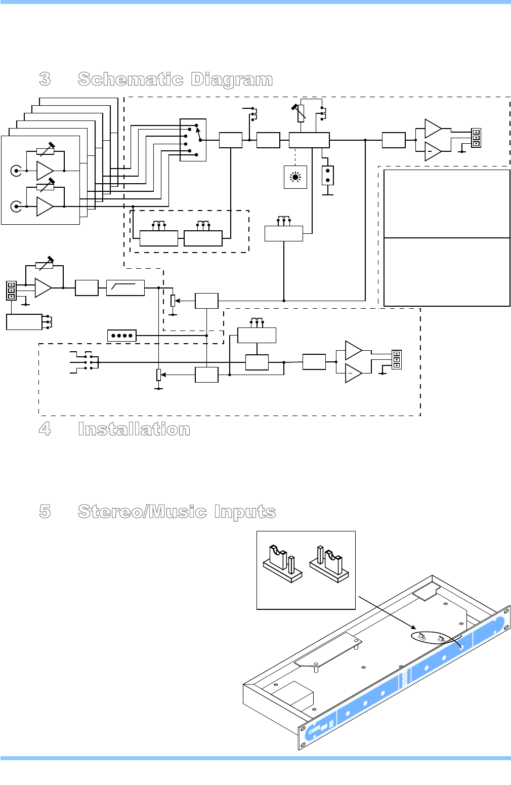
- 3 Schematic Diagram 8
- 4 Installation 8
- 5 Stereo/Music Inputs 8
- REMOTECONTROLOFMUSICLEVEL 9
- Music Level Control continued 10
- 6 Microphone Input 11
- 6.2 Microphone Gain Control 12
- 6.3 Microphone Level Controls 12
- 6.4 Microphone Equalisation 12
- 6.5 High Pass Filter 12
- 7 Output Details 13
- 7.1 Utility Output 14
- Installation: 15
- Current Consumption: 15
- 10 Technical Specifications 16
- 1 General Specifications 16
- 12 Troubleshooting 17
Related products and manuals for Audio Cloud-electronics CX163
 (16 pages)
(16 pages)
(16 pages)
 (16 pages)
(36 pages)
(16 pages)
(16 pages)
(16 pages)
(36 pages)
(16 pages)
 (56 pages)
(12 pages)
(20 pages)
(23 pages)
(11 pages)
(79 pages)
(56 pages)
(23 pages)
(28 pages)
(56 pages)
(12 pages)
(20 pages)
(23 pages)
(11 pages)
(79 pages)
(56 pages)
(23 pages)
(28 pages)
© 2020, manymanuals.com. All rights reserved. | 0.057 s |
 Manymanuals.com
 Manymanuals.de
 Manymanuals.fr
 Manymanuals.it
 Manymanuals.pl
 Manymanuals.cz
 Manymanuals.es
 Manymanuals-pt.com
Comments to this Manuals